NASA JPL:
SWOT Satellite Thermal Engineering
How do you fit space in a box?

Project Introduction
During the summer of 2019, I joined the JPL Surface Water Ocean Topography (SWOT) satellite thermal engineering team to assist in satellite integration and thermal testing. I designed, fabricated, and tested ground support equipment (GSE) that will allow the SWOT team to simulate space-like environments in JPL’s vacuum test chamber.
Note: all images have detail captions explaining data presented. To access them, click on the image.
Background: Radiative Heat Exchanger
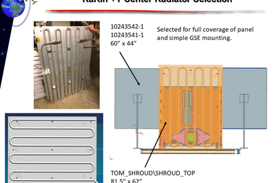
Radiative fluid loop heat exchangers (HX), pictured above, are the industry standard for radiative thermal control in aerospace vacuum testing. HXs are plates as large as a dining room table. On one side, they have pipes braised on through which flows a combination of liquid nitrogen (LN2) and hot nitrogen gas (GN2). By varying the flow rate and temperature of the fluid, we can simulate the temperatures we expect to see just outside the satellite in space.
Key Objective
When I first arrived, I was given data from the worst case thermal simulations of the satellite and essentially told “Go find out if we can do this in a lab. We’d like the answer to be ‘yes.” There were two key questions that I had to answer to answer this overall question:
-
Can we make the thermal gradients across the HX small enough?
-
Can we drive the heat exchangers fast enough to make the test match the simulation?
Heat Exchanger Configuration Development
After building my background knowledge of heat transfer, spacecraft thermal analysis, thermal vacuum testing, and two-phase fluid systems, I then specced out the HXs we would be using in testing. I chose to find and refurbish some old HXs, as opposed to designing and fabricating new custom HXs, which wound up saving the team $10,000-$20,000 in development costs.
Computational Thermal Modelling
After building my background knowledge of heat transfer, spacecraft thermal analysis and testing, and two-phase fluid systems and selecting a promising heat exchanger configuration, I built several analytical computational models of radiative heat exchangers and two-phase fluid heat transfer in AutoCAD Thermal Desktop. Once the base model had the correct physical characteristics of the HXs, I began to tune the model by gathering more information about the system. We eventually reached a point where the only way to get the last critical parameter—the flow rate—was to take the heat exchangers up to the lab and test them in vacuum-like conditions.
Thermal Testing
I assumed the role of cognizant test engineer to coordinate their refit to the test configuration and run performance testing on the HXs. I managed a team of technicians and test operators to design and complete the HX characterization testing campaign within the last two weeks of my internship. I developed this set of test objectives and designed the tests that would accomplish them:
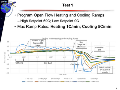
Test 1-drive the HX at max heating and cooling ramp rates
-
Define maximum LN2 and GN2 flow rates
-
Characterize thermal gradients across the HX in steady state and transient conditions
-
Define maximum heating and cooling ramp rates to assess whether we could meet our goals
-
Develop techniques for operating the lab’s control system in transient conditions
Test 2-Cycle the HX at max rates defined in Test 1
-
Identify differences in transient performance resulting from multiple thermal cycles
-
Characterize thermal gradients under operation-like conditions
-
Confirm validation of controller procedures
Results
After testing, I analyzed the data in Matlab and Excel and then modified my thermal model to use the new input values discovered in testing. The ballpark values that had been estimated by other engineers and technicians turned out to be nearly an order of magnitude higher than the actual flow rates we were seeing in testing. This made the thermal gradient performance of the heat exchanger decline to a level that made the test environment untenable.
I presented the analysis and conclusions to the rest of the team. We determined that no matter what heat exchanger configuration we chose, the test data showed that our current lab setup did not have high enough performance to achieve the rapid heating and cooling ramps while still keeping thermal gradients within acceptable limits. Even though the transient test was scrubbed, the hardware I developed would still be used in the team’s other steady state tests.
Additional Project:
Heater Plate Design
In parallel with my main project, I also completed several other secondary projects, including designing other pieces of GSE for the upcoming test campaign. This heater plate is designed to go underneath the satellite modules during testing and simulate the heat transmitted from other parts of the satellite. It uses an array of kapton resistance heaters instead of a fluid loop system. This allows for much finer control within a smaller temperature range.
My goal here was to minimize the thermal gradient across the plate at a reasonable cost. I used Thermal Desktop to test different heater configurations. I then designed the support structure for the plate and drafted fabrication and assembly drawings.


